I'm not quite ready to start this one in earnest but since I just received the conversion set from Laminar Flow Designs, I was excited to take a peek and at least set this build up for the near future. I started following Matthieu on Facebook as he was developing plans to convert the Tamiya XVIe kit into a Griffon-powered XIVe using digitally-printed parts. I've always found the five-prop Griffon-powered Spitfires to be especially fascinating and patiently waited until development of this project turned into an actual product.
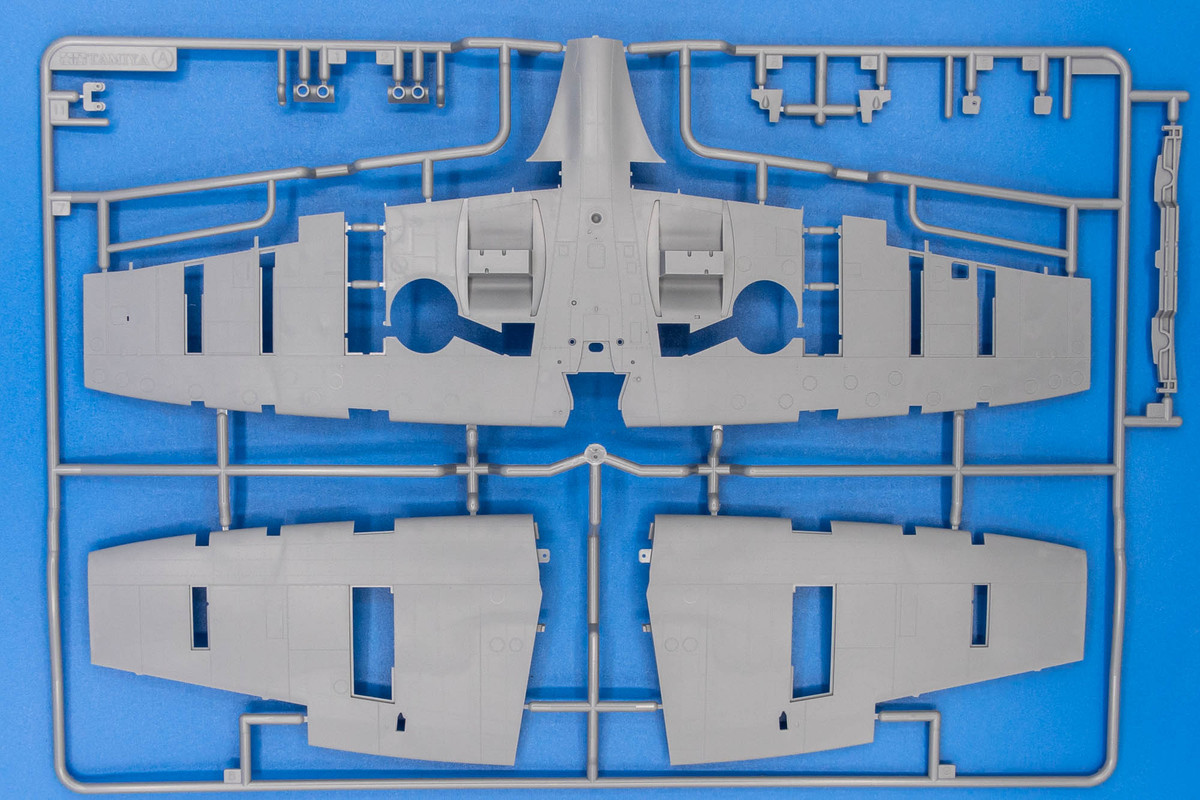
I've had the Tamiya XVIe kit on the shelf for several years now.
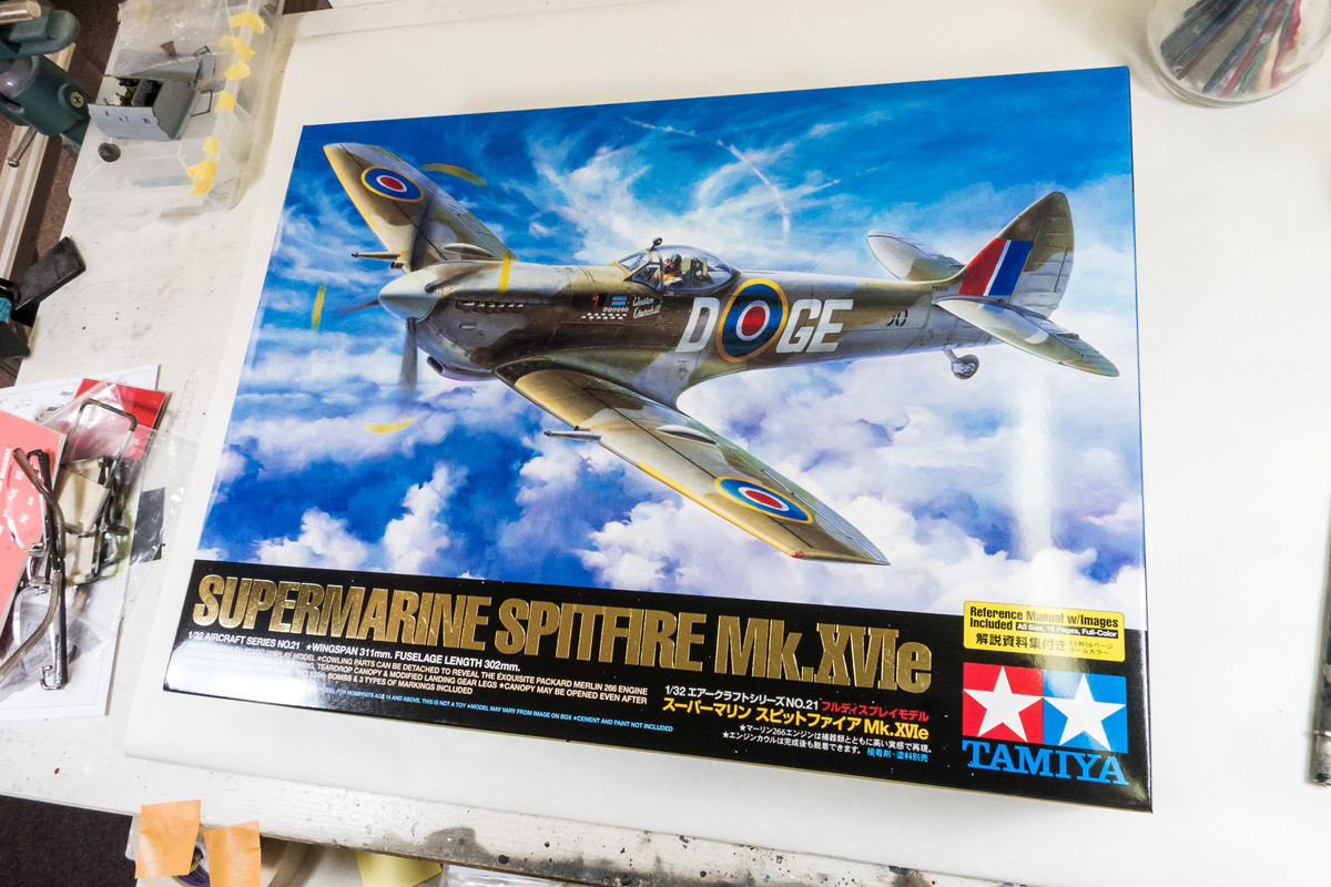
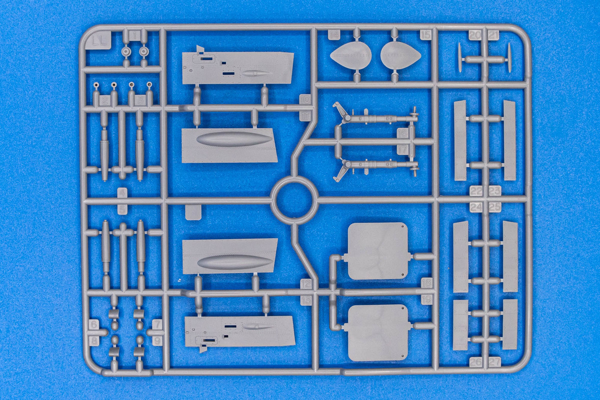
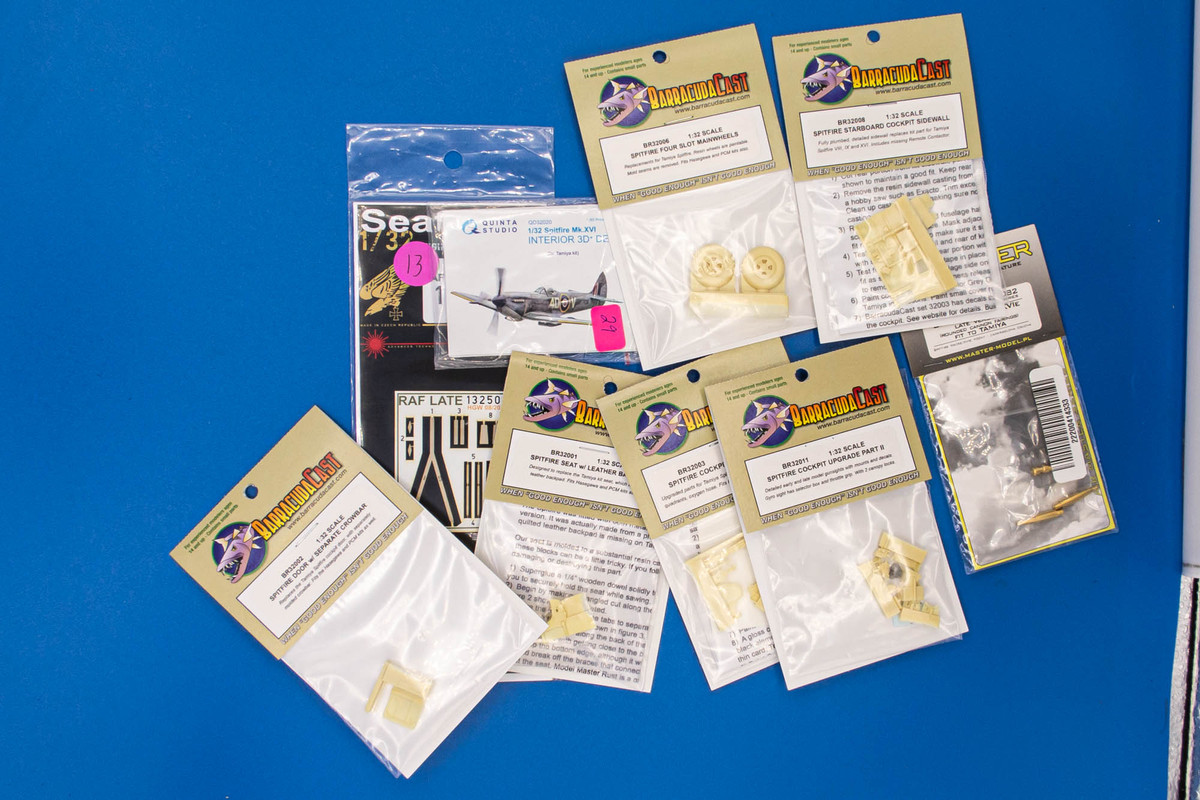
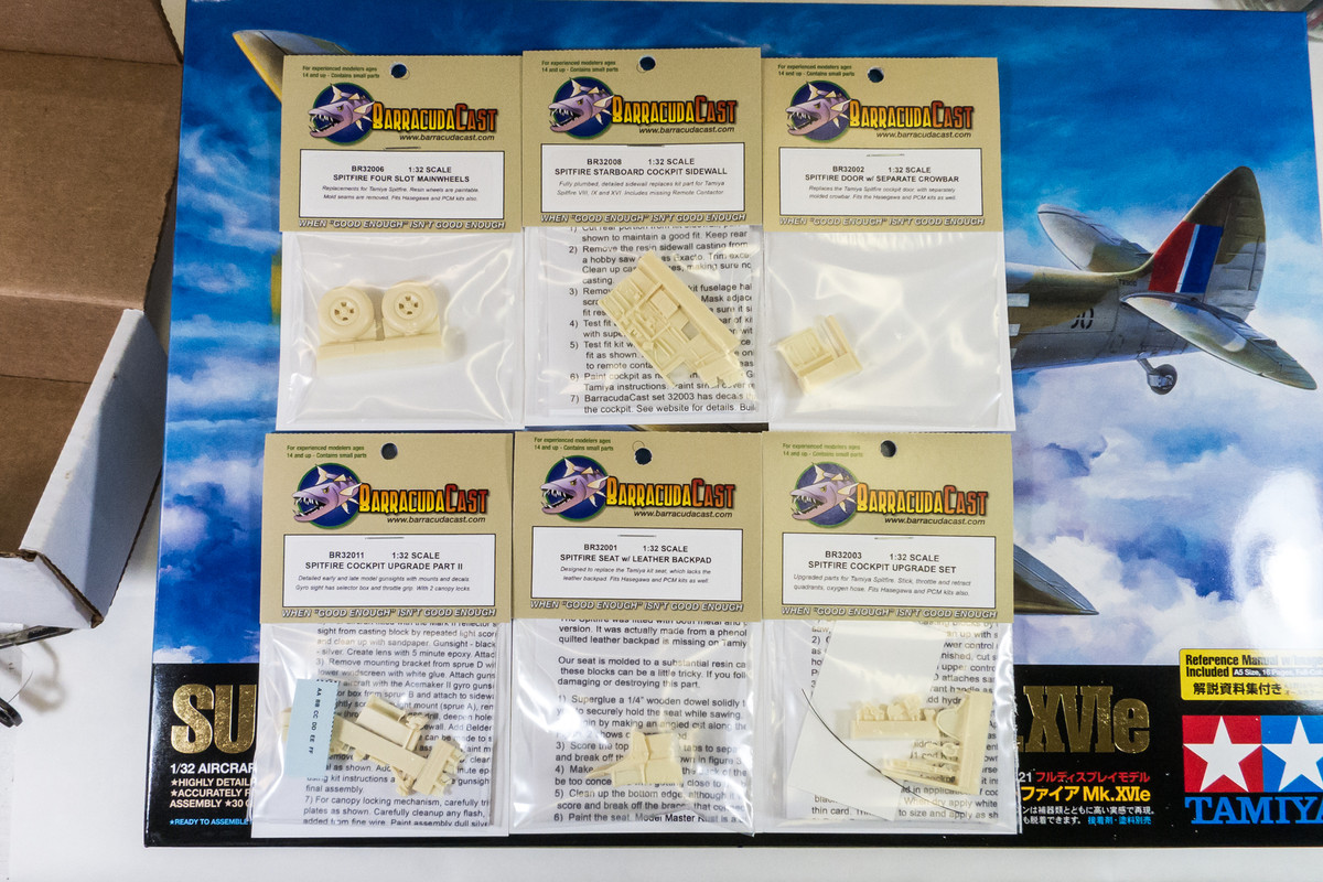
Prior to learning about the XIVe conversion, I was planning to build it as kitted and picked up a few aftermarket items from Barracuda, as well as some brass gun barrels from Master.
But today, I received this little box from Belgium!
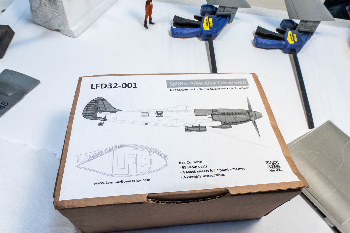
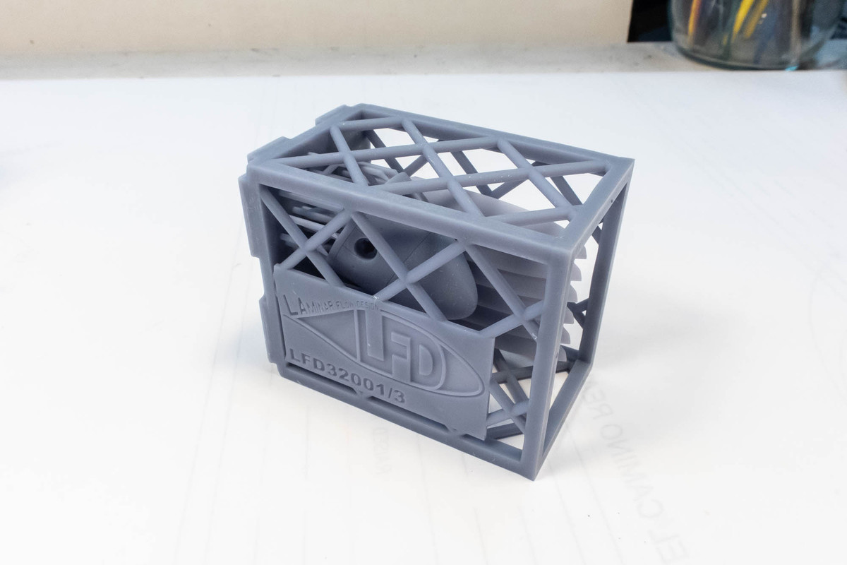
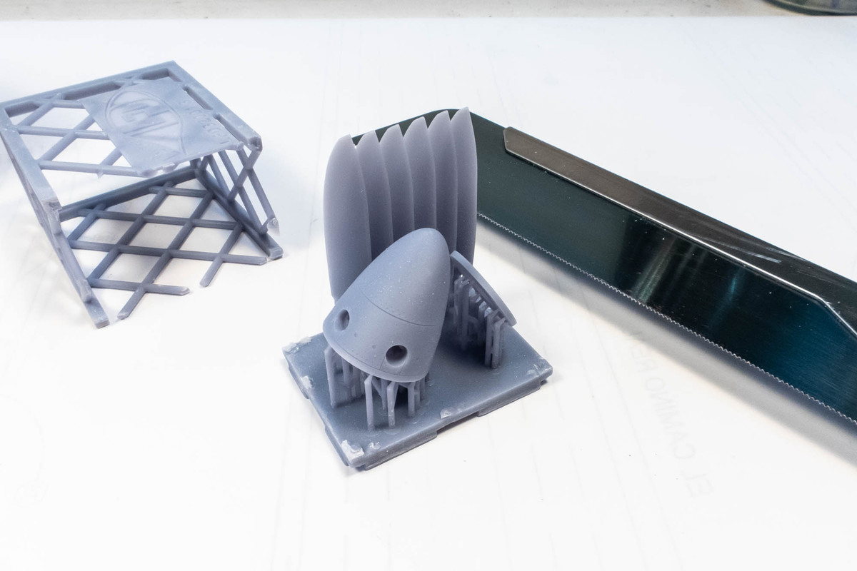
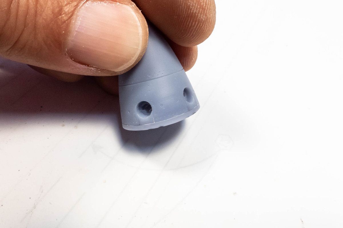
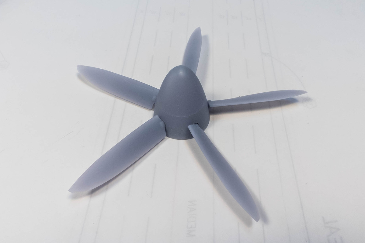
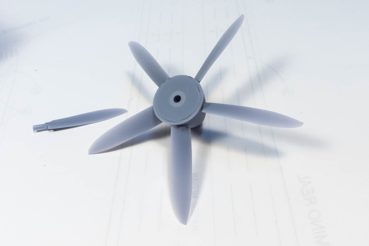
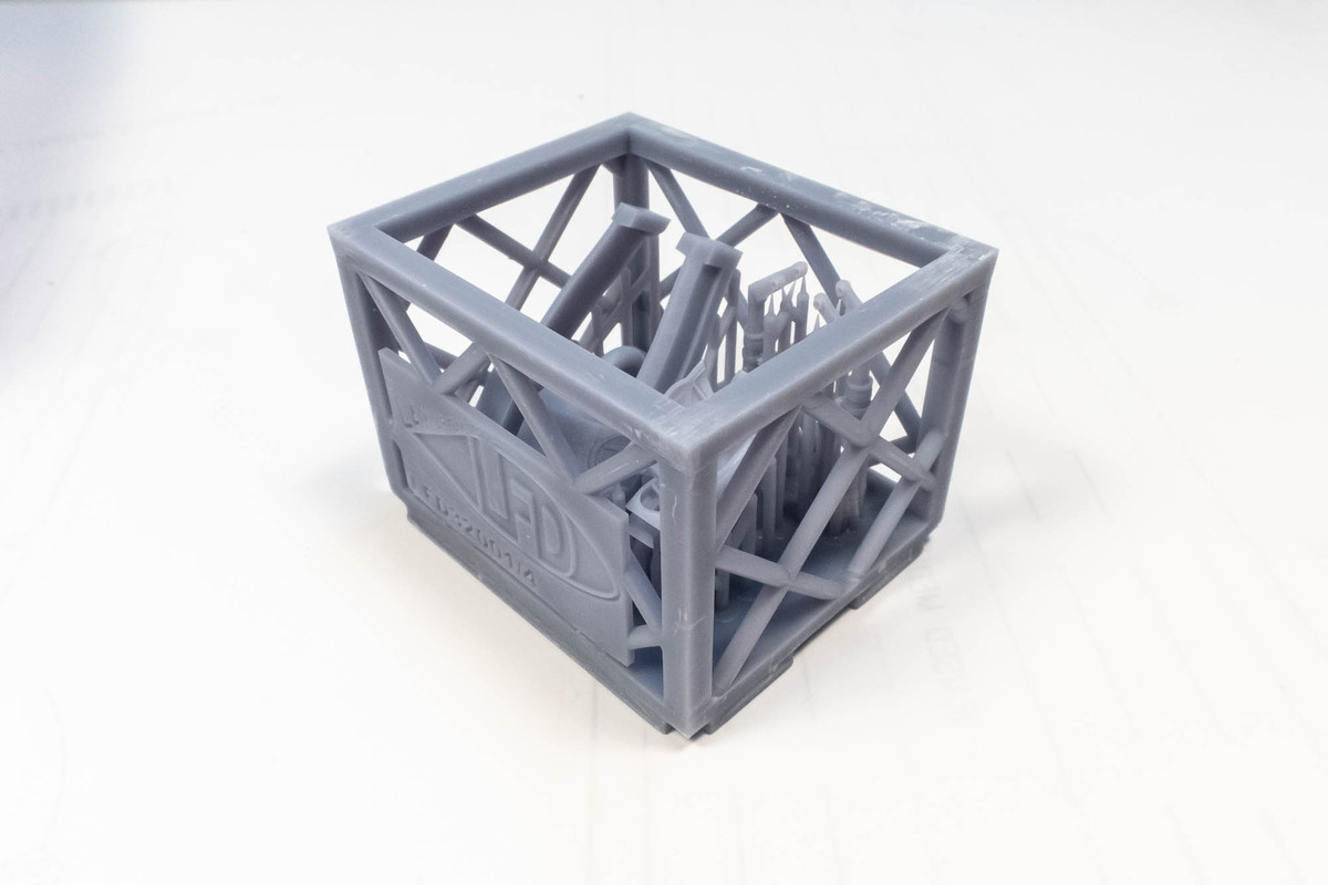
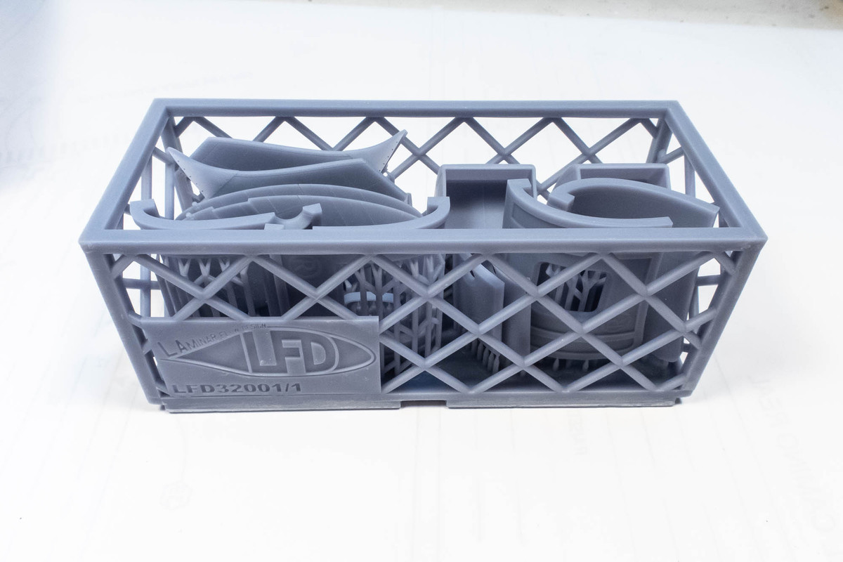
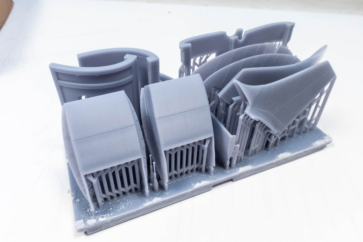
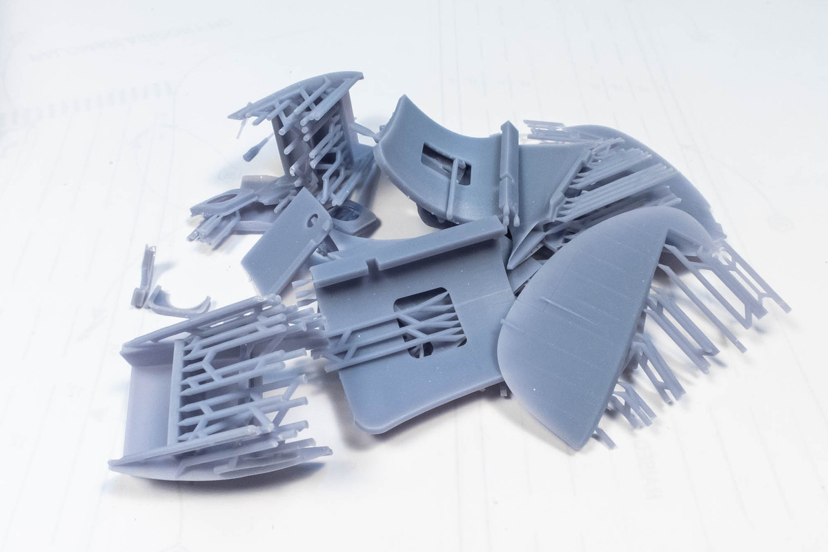
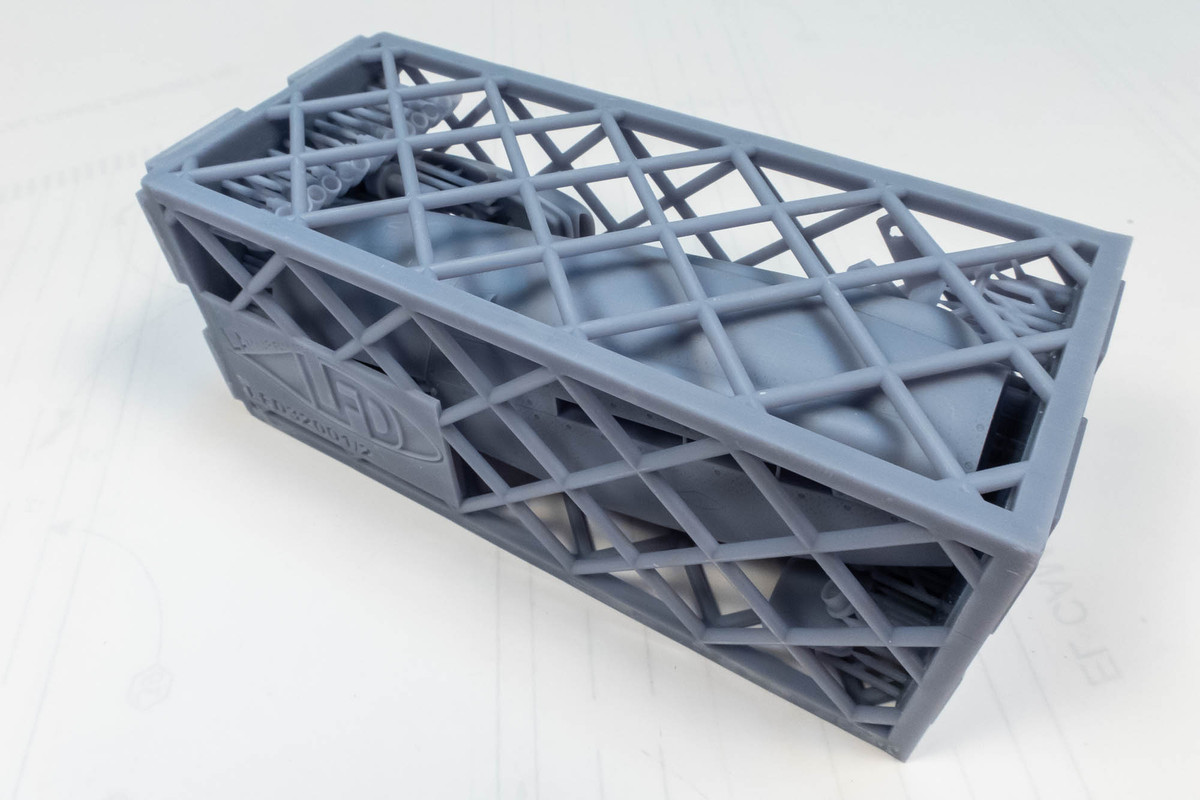
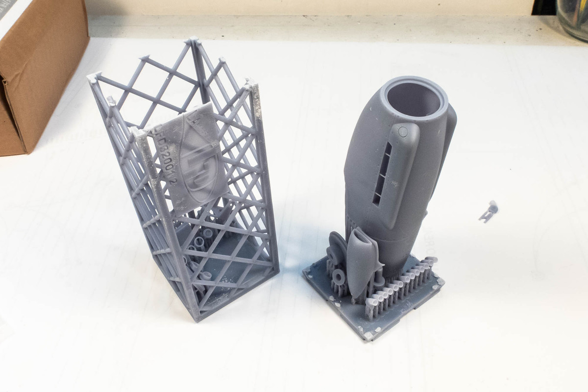
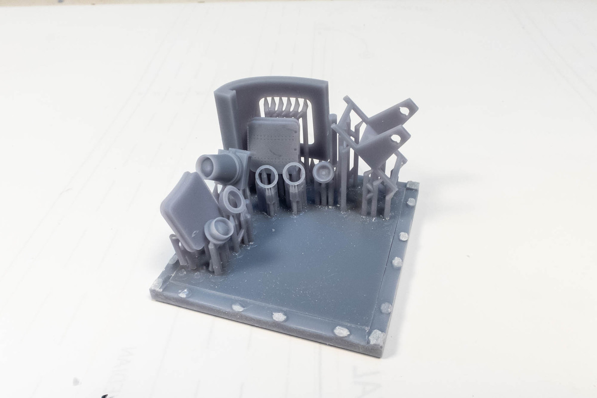
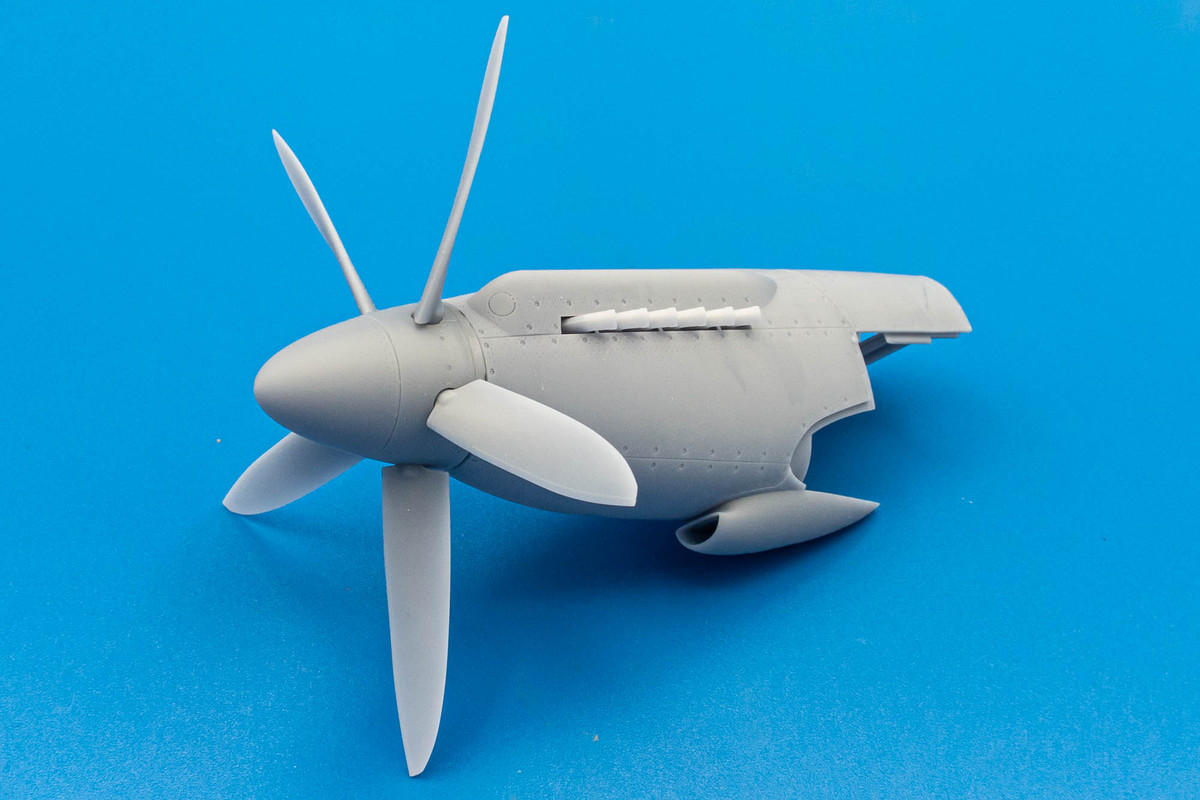
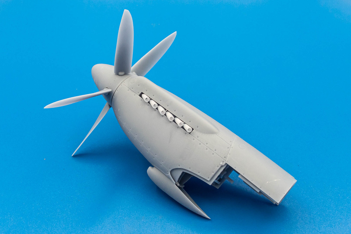
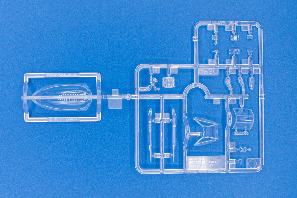
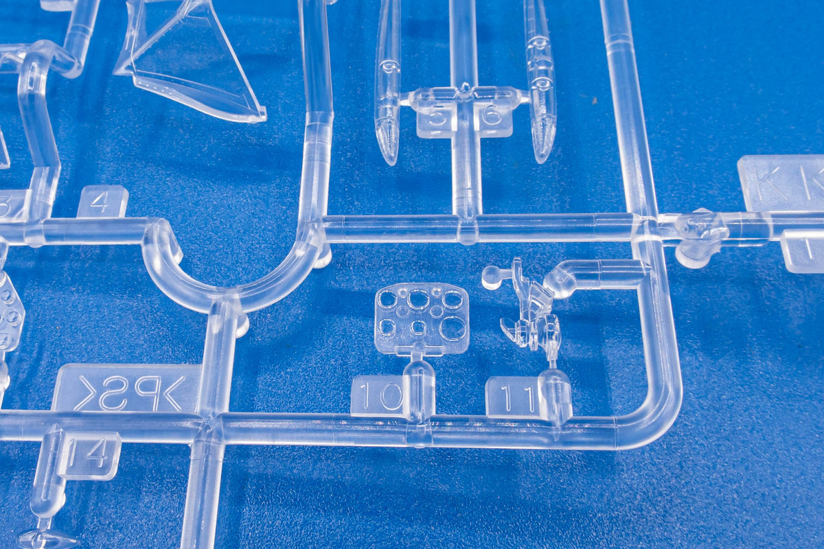
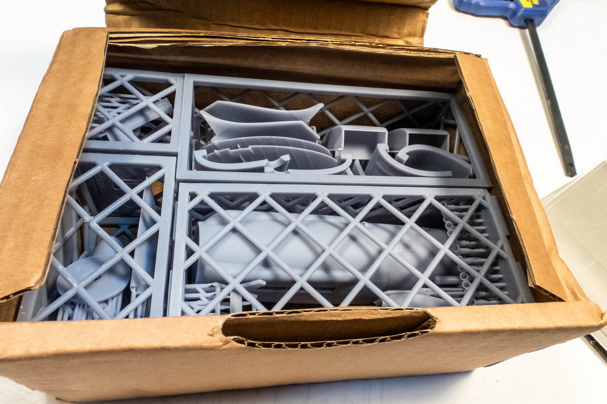
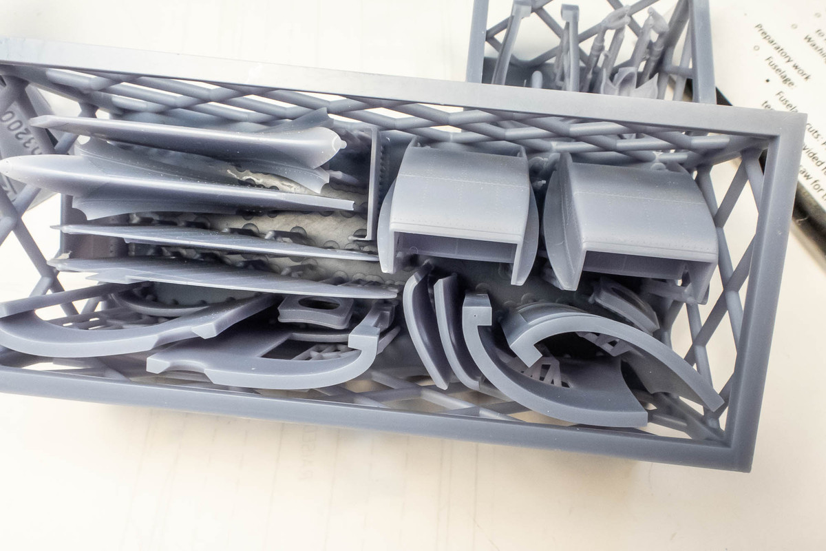
It packs a lot of stuff into a very small space, thanks to very clever production design. The parts are digitally printed within four separate cages to protect them during shipment. The four cages are designed to fit perfectly in the box.
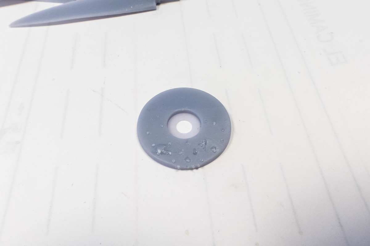
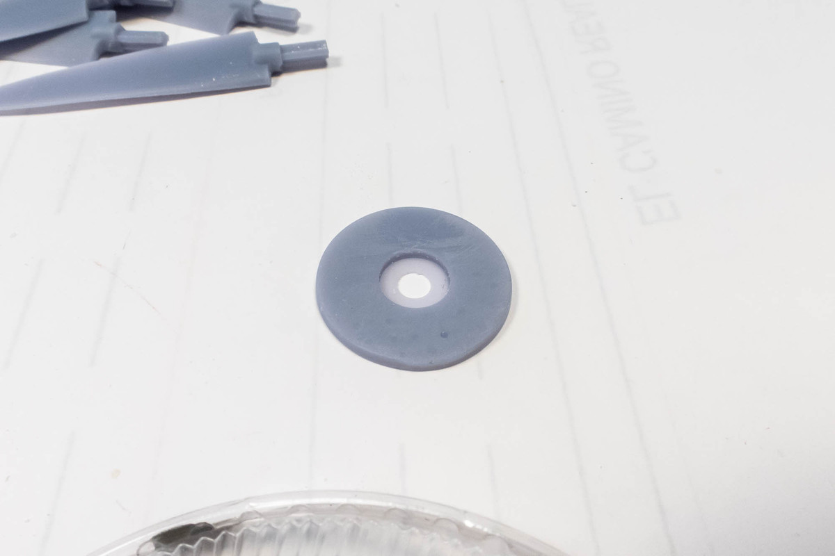
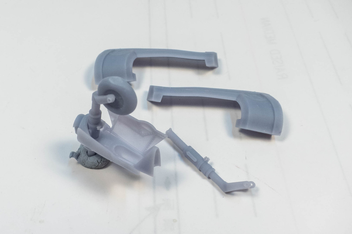
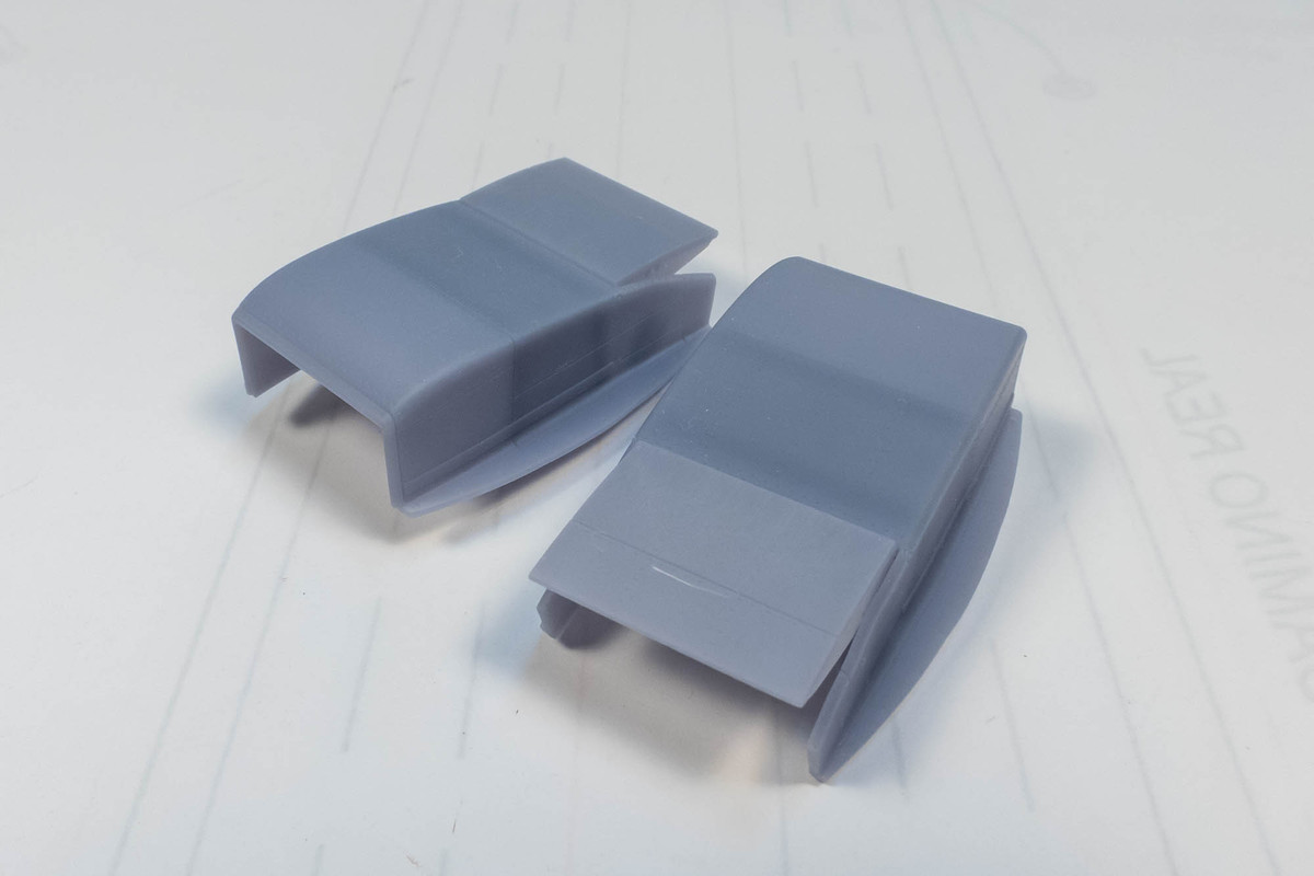
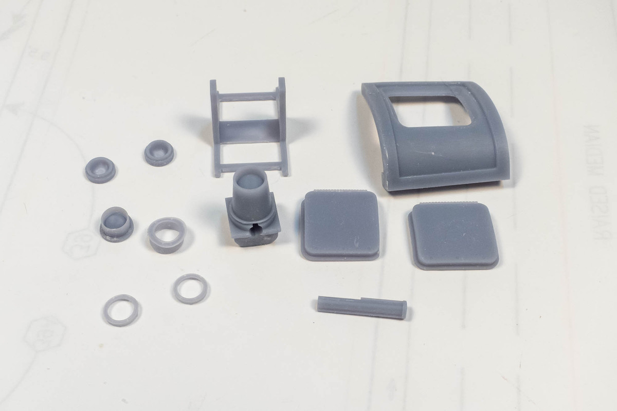
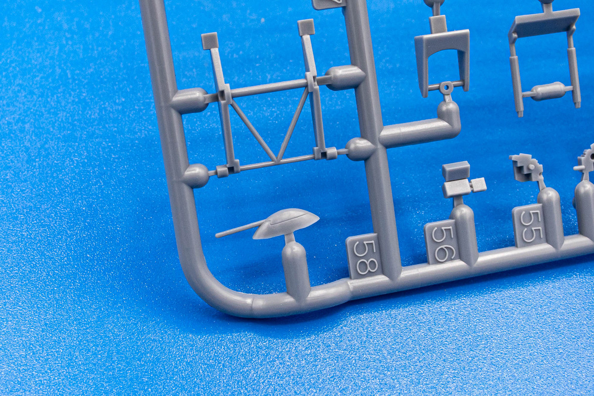
To my surprise, I found some loose parts in my box.
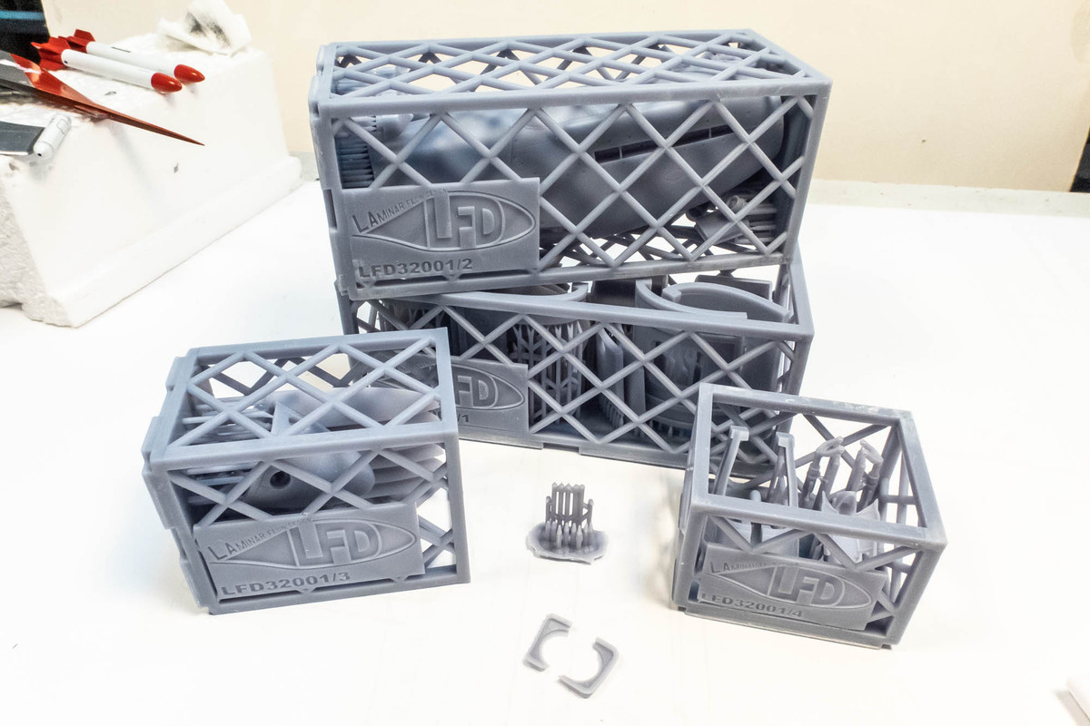
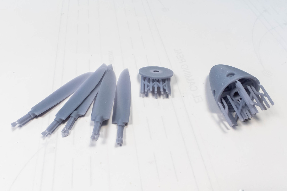
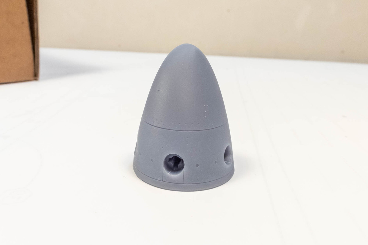
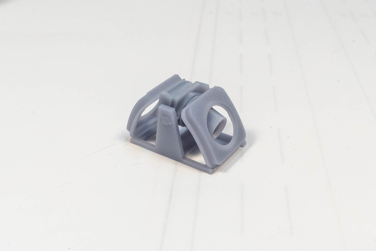
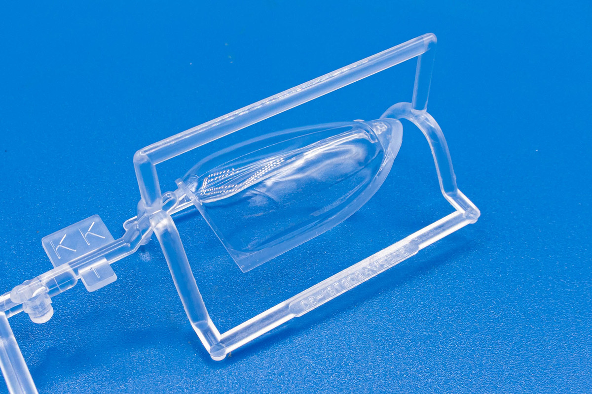
Strange... it appears to be one of the camera fairings for the FR variant.
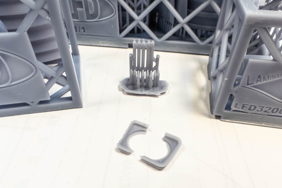
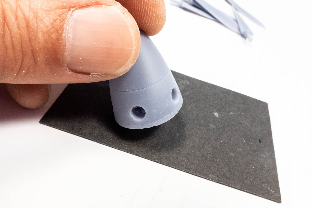
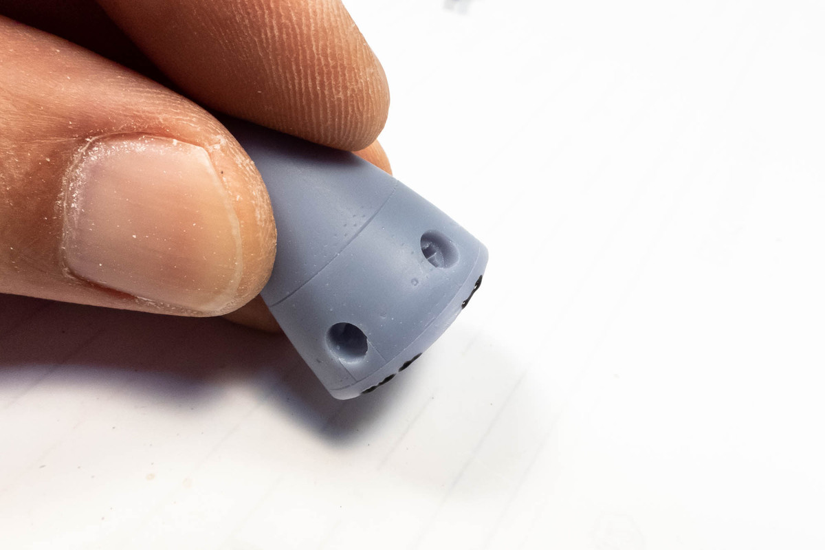
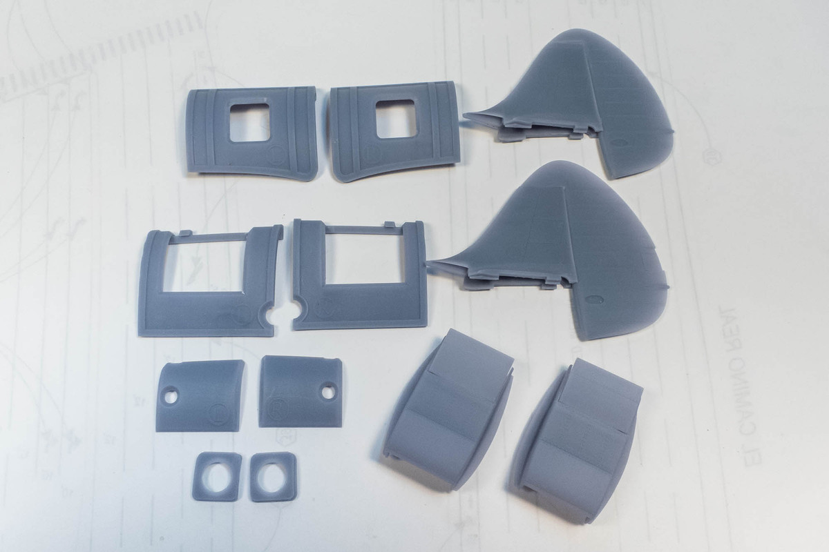
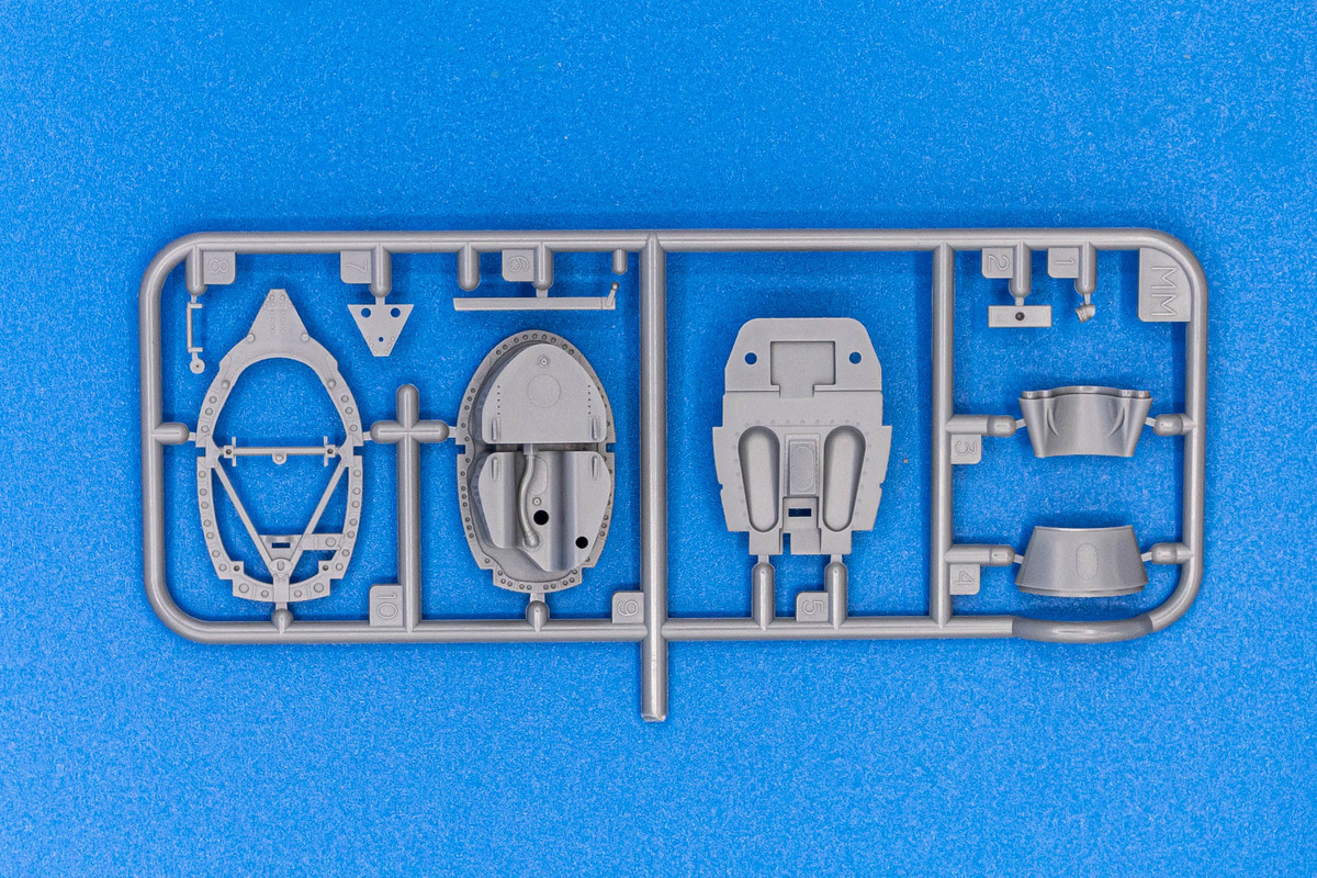
But when I peek into Cage #4, I can make out two camera fairings intact.
Unless there are more than two of these fairings in this set, I believe that the broken fairing and its support base got tangled up into this shipment during the packing phase. I'll contact Matthieu to inquire but I'm not too worried about it because my initial plans are for the fighter variant and I won't need the camera fairings anyway.
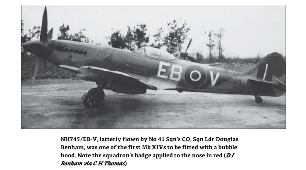
This is the aircraft that I've initially selected as my subject.
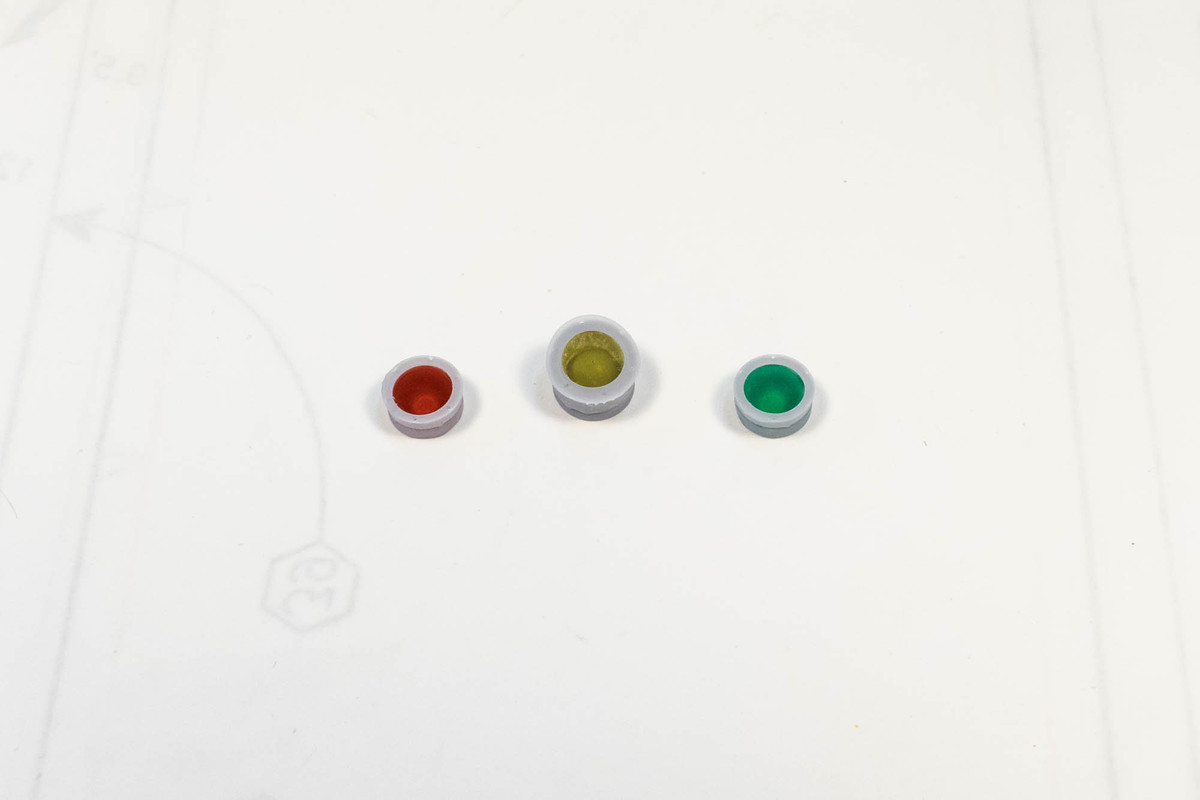
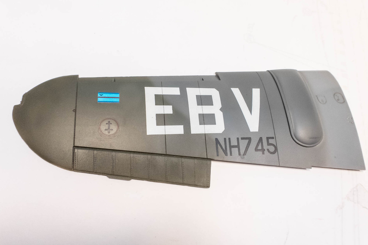
As an initial step, I wanted to see if I could fabricate the specific markings for this aircraft using a combination of custom cut masks for the larger markings and custom decals for the small squadron badge beneath the exhausts and the squadron leader flag under the windshield. The masks were created in AutoCAD and cut with a Silhouette Portrait and the decals were mocked up in Powerpoint and printed onto decal paper (Microscale).
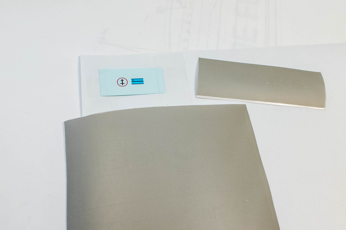
Due to the lack of opacity of the printed decal, I had to paint a white box as a background for the squadron leader flag.
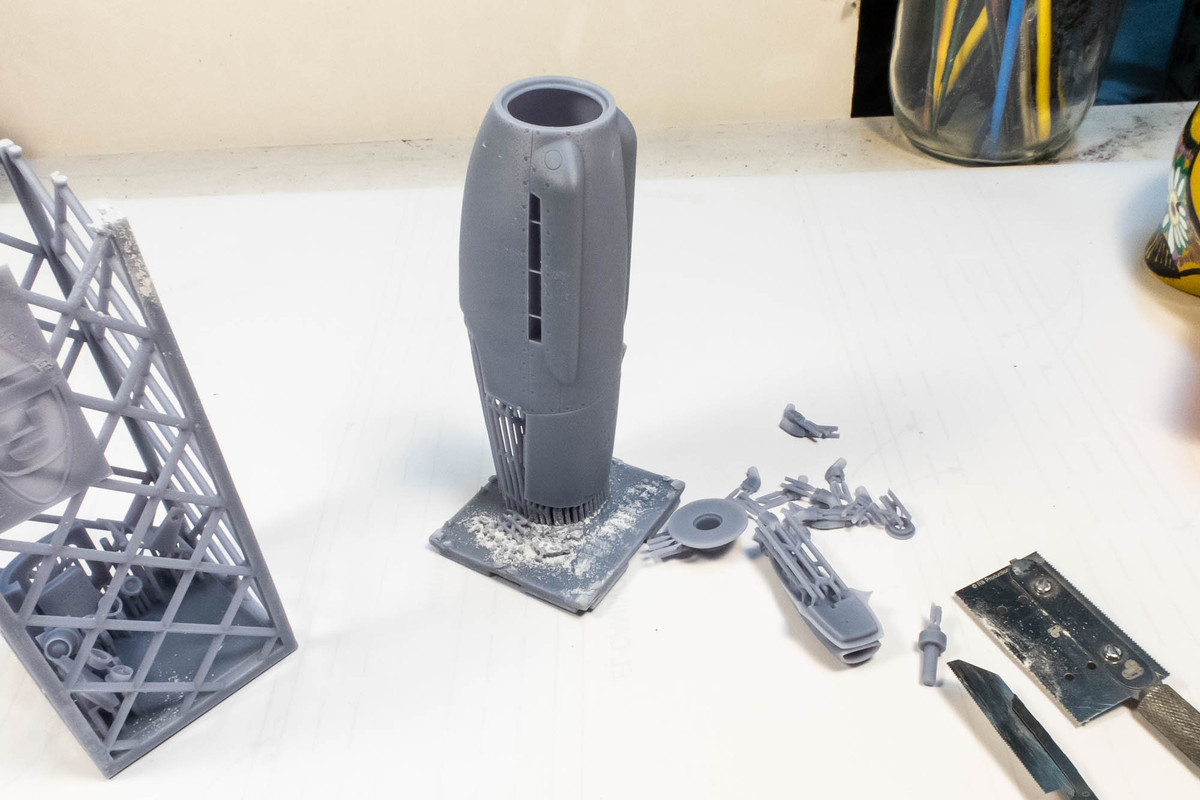
That's it for now. This will be my first experience using 3D printed parts so I'll probably be asking some newbie questions along the way. Like... are these digitally printed parts made from resin? Do I treat them the same cast resin parts?
Tamiya 1/32 Spitfire XIVe Conversion
John aka JKim
-----------<><
-----------<><
- tempestjohnny
- Elite Member
- Posts: 3416
- Joined: Sat Oct 15, 2016 4:51 am
- Location: Naples. FL
Re: Tamiya 1/32 Spitfire XIVe Conversion
While I get ready for the painting stage on my Border 190A build, I am going to jump back onto the Spitfire project. And before I even get to the actual Tamiya parts, I want to take a closer look at the Laminar Flow Design conversion parts. Being my first experience with digitally-printed parts, I was especially curious on how to separate the parts from their interesting "crates". Let's start with the prop components. There is something about a five-bladed prop fighter that intrigues me visually and I was really excited to have a chance to model a large scale XIVe. I followed the instructions which said I sould remove the four crate walls from the base to access the parts.
The parts are suspended by a myriad of support columns and each support must be cut from the part. I chose to use a fine razor saw and saw the support columns near the base to, working from outside to the inside. Because the connections to the parts are very small, some of the braces broke off the part during the sawing process. I don't know how to prevent this but it didn't seam to affect the parts negatively.
Once each part was separated from the base, I snipped off each of the supports. Similar to cutting styrene parts off of a sprue except 10x more connections. I don't know anything about the digital printing process but as an end user, I see that placement of the supports is important. Cutting the connections tends to leave either raised stumps or if they've broken instead of being cut, a small divot. The resin at the connection points is noticeably harder, making the clean-up process more difficult. In this case, all of the attachment points are on the glue-side of the spinner backplate.
I noticed slight imperfections on the edge of the spinner. Not around the entire perimeter but in certain spots only.
I wasn't sure of the best way to rectify this but I chose to fill the imperfections with black CA glue.
A really nice touch are the keyed holes for the prop blades. There is only one way to insert the blades into these holes, ensuring proper orientation and blade angle.
Here is the prop with the blades temporarily inserted into spinner. An extra blade is provided. The scribed detail on the spinner is VERY fine and I think I'm going to need to be careful not too fill in the detail with too much paint.
The next batch of parts to break out of prison are the tailwheel components. There were two tiny rods, presumably the actuating rods for the tailwheel doors, that were lost. Strange because I identified them prior to cutting, paid very particular attention as I cut and they pinged into thin air, one after the other. No biggie... very easy to replace with stretched sprue.
Here are the tailwheel parts after cutting and clean-up. In addition to the one-piece tailwheel well and open doors, two struts and a weighted wheel, LFD provides resin templates for the fuselage cuts necessary to accommodate the assembly.
This box was the most densely packed and most challenging to deal with.
After the walls of the crate were removed, I started sawing the supports at the base. Because each part had multiple rows of support connections, it was difficult to do this in an orderly fashion. Lots of dust (make sure you wear your mask) and lots of supports breaking off of parts as I was cutting. See the two tiny rods between the radiators? I was able to save those!
Each separated part was thrown into a pile until I was able to free everything from the base.
Here are the parts after clean-up. No external or visible scarring from the connection points... kudos to Mathieu for placing them so strategically.
The detail on the parts is incredibly fine... trailing edges are paper-thin. Two types of tail fins are supplied... wide and extra wide!
The radiator faces have a fine mesh pattern that looks to be too fine to hold a wash or to dry-brush.
I'm saving the biggest part for last... the big Griffon nose.
John aka JKim
-----------<><
-----------<><
Re: Tamiya 1/32 Spitfire XIVe Conversion
Let's free the biggest piece of the set... the Griffon nose. This time the cage is double-load with attached parts on both ends.
Again, working from the outside to the middle, the support trees are sawed near the base to free each part.
Here is the nose piece with the exhaust stubs and chin intake pressed into place after these parts have been cleaned up.
The opposite base has a lot of small, delicate-looking parts so care must be taken when cutting these free.
Here are the parts after trimming and sanding. Lights and the camera assembly are included.
I don't think I'll be doing a recon version so this camera and circular ports will most likely not be used.
The lights are comprised of the bulb/reflector and the external mounting ring. A 4mm clear acetate disk, which I punched and painted in clear red, yellow and green, are sandwiched between the two parts.
All of the separated resin parts will be bagged for later use. I'm going to take a look at the Tamiya XVIe kit parts next. But here is a sneak peak at the resin nose with the prop and and other bits attached temporarily.
John aka JKim
-----------<><
-----------<><
Re: Tamiya 1/32 Spitfire XIVe Conversion
Time to get familiar with the Tamiya kit. I'm going to look at some of the sprues just to get the lay of the land. Since this is a conversion to a Griffon-powered XIVe, I'm going to skip over the Merlin engine parts for obvious reasons. Using the conversion may actually simplify this build!
First up is the wing sprue. XVIe kit converted to an XIVe... assuming that there are no major changes on the wing.
As typical of recent Tamiya kits, the molding detail is exquisite and I have no fear that the various inserts for the wing panels will fit well.
More control surfaces on this sprue. I assume that this includes the wing tips for the non-clipped wing version of the E-wing.
A comparison between the Laminar Flow Design resin rudder and the kit rudder. I'm sure the kit cannot match the thinness of the resin since the rudder, like the other control surfaces, is molded in halves.
Here is ithe low-back Spitfire fuselage.
I think this hatch goes away with the XIVe conversion. It will be a challenge to restore the fine panel line and rivet detail.
I have the Quinta cockpit for the XVIe so I'm pretty sure I won't be using the kit instrument panel but it looks to be molded well with lots of 3D-relief.
I assume this sprue is specific to the bulkheads associated with the low-back Spitfire.
The other internal components including the cockpit are on this sprue.
From my understanding, the XIVe cockpit is different than the XVIe and is more similar to the VIII. So I am doing a little research into the cockpit specifics of the VIII/XIV types.
The clear parts including the clipped wing tips and the bubble canopy.
The bubble has a subtle molding ridge down the middle that will need to be polished away.
The central instrument cluster is represented in clear plastic. I've never liked this approach to instrument panels as the molded clear plastic is too thick. I've got the Quinta panel anyways so this won't be an issue.
Some external components including the gun panel covers for the wing.
Landing gear legs look pretty basic.
Wheel well parts on this sprue and what looks to be more landing gear legs?
Some detail parts provided on a metal sprue. I've got the HGW fabric seatbelts so I don't have to use the stiff metal belts.
And here is the aftermarket list of items I have available. This includes:
1. Barrcuda Spitfire Cockpit Upgrade Set (BR32003)
2. Barracuda Spitfire Cockpit Upgrade Set Part 2 (BR32011)
3. Barracuda Spitfire Starboard Cockpit Sidewall (BR32008)
4. Barracuda Spitfire Seat with Leather Backpad (BR32001)
5. Barracuda Spitfire Door w/ Crowbar (BR32002)
6. Barracuda Spitfire Four Slot Mainwheels (BR32006)
7. Master Spitfire IXe, XVIe Late Gun Barrels (AM32-082)
8. Quinta Spitfire XVI 3D Interior (32020)
9. HGW RAF Late Seatbelts (132503)
10. Aviaeology Spitfire Airframe Stencils Decal Sheet
John aka JKim
-----------<><
-----------<><
- tempestjohnny
- Elite Member
- Posts: 3416
- Joined: Sat Oct 15, 2016 4:51 am
- Location: Naples. FL
Re: Tamiya 1/32 Spitfire XIVe Conversion
Great looking printed parts John. I've got my first bits from Barracuda and I'm very impressed. I hope the expand their product line.
Thanks,
John
John
- BlackSheep214
- Elite Member
- Posts: 10553
- Joined: Sun Apr 06, 2014 8:47 pm
Re: Tamiya 1/32 Spitfire XIVe Conversion
“Who controls the skies, controls the fate of this Earth”
Author unknown- 352nd Fighter Group, Blue-Nosed Bastards of Bodney
“Send one plane it’s a sortie; send two planes it’s a flight; send four planes it’s a test of airpower. - Richard Kohn
Author unknown- 352nd Fighter Group, Blue-Nosed Bastards of Bodney
“Send one plane it’s a sortie; send two planes it’s a flight; send four planes it’s a test of airpower. - Richard Kohn
- Stikpusher
- Moderator
- Posts: 19020
- Joined: Sat Apr 05, 2014 8:37 pm
- Location: Ceti Alpha 5
Re: Tamiya 1/32 Spitfire XIVe Conversion
A Spitfire getting the JKim treatment. This will be good
"Surely I have made my meaning plain? I intend to avenge myself upon you, Admiral. I have deprived your ship of power, and when I swing 'round, I intend to deprive you of your life."
FLSM
FLSM
Re: Tamiya 1/32 Spitfire XIVe Conversion
Thanks guys! Don't know much about Spitfires so I'll be winging it on limited information. Oh... the mystery part that I inquired about on Carlos XIVe build is included in the kit so no need to scratch up the Beam Approach Aerial...
John aka JKim
-----------<><
-----------<><